
COMPLETE GUIDE TO FLASHING THE MUCAR ADAPTER TO X-DIAG PRO
The MuCar adapter is an OBD device used for professional diagnostics. Flashing is performed to upgrade firmware, fix operational issues, or migrate the adapter to platforms such as X-Diag PRO. For advanced firmware versions, physical connection to a programmer (ST-LINK V2 or J-Link) may be required.
Opening the Housing
The DBScar 7 comes in a solid plastic housing joined by clips. To open it, it is best to use a plastic prying tool (such as one for phone disassembly) or a thin plastic lever. A screwdriver can also be used but often leaves damage, so it should be avoided. First, remove the rubber cover if present. Then locate the seam along the middle of the housing. Small clips hidden there hold the top and bottom parts together. Carefully insert the tool into the gap between the plastic pieces and gently pry them apart. It is best to start on the side opposite the OBD connector and work your way around until all clips are released. Take your time—if a clip breaks, the housing will not close properly later. Once opened, you will see the printed circuit board (PCB) with its components. On it is an STM32 microcontroller, next to which are test points intended for programming.
Preparation
Before starting, prepare the following:
- Android device or computer
- MuCar adapter
- Correct firmware file for your MuCar model (usually .bin)
- ST-LINK V2 or J-Link programmer for advanced flashing
- Soldering iron, thin wires, or small crocodile clips for PCB connection
- Stable power supply for the adapter (vehicle battery or USB programmer)
Ensure your phone or computer has sufficient battery, and disable any nearby Bluetooth devices if using wireless connection.
Opening the Housing
The MuCar adapter has a plastic housing held together with clips. Use a thin plastic prying tool or phone-opening tool to open it.
Remove the rubber protective cover if present.
Insert the prying tool between the top and bottom parts and gently release the clips.
Work around the housing until all clips are free.
Once open, you will see the PCB with the microcontroller and test points for programming.
Connecting to the Programmer
On the MuCar PCB, locate the flash pins: GND, 3.3V, SWDIO, SWCLK.
Connect them to an ST-LINK V2 or J-Link programmer pin-to-pin:
GND → GND
3.3V → 3.3V
SWDIO → SWDIO
SWCLK → SWCLK
If using a soldering iron, solder thin wires to the pads. If not, small crocodile clips or pins can be used, but connections must remain stable. Double-check the pin layout to avoid damaging the microcontroller.
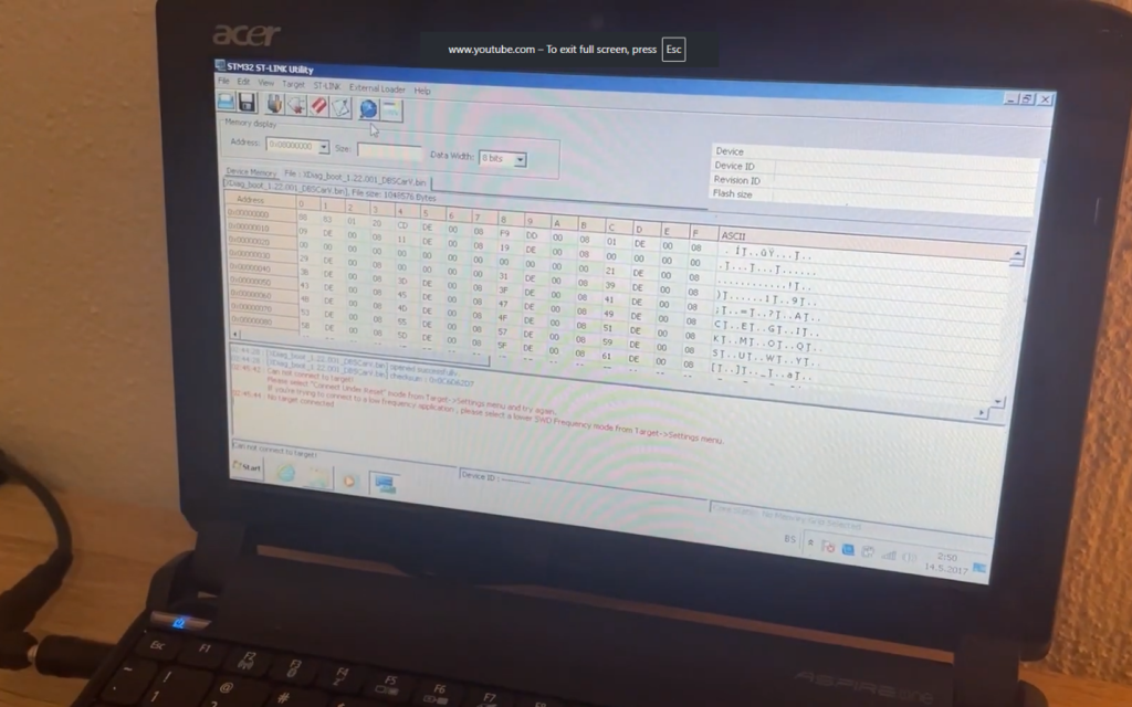
Flashing the Firmware On your computer, launch STM32 ST-LINK Utility. The software should detect the MuCar microcontroller. Select “Program” or “Load File” and load the firmware file for MuCar (.bin). Click “Start” and wait for completion. Do not move wires, disconnect the computer, or remove the adapter during the process. Flashing typically takes less than a minute. When the program confirms a successful write, the flash is complete.
Closing the Housing and Verification
Disconnect the programmer wires and carefully place the PCB back into the housing. Close the housing so that all clips snap into place.
Plug the MuCar adapter into the vehicle’s OBD port and launch X-Diag PRO or the MuCar app. Log in, enable Bluetooth, and connect the adapter. If prompted, enter the default code, usually 1234 or 0000. Once recognized, run a diagnostic on a vehicle to confirm proper operation.
Troubleshooting
- If the software does not detect the microcontroller, check the connections and power supply.
- If flashing stops midway, try again.
- If the adapter is unresponsive after flashing, incorrect firmware may have been used; reflash with the correct file.
- If Bluetooth fails to connect, delete the old pairing on your phone and pair again.
Summary: The MuCar adapter is opened using a plastic prying tool, connected to ST-LINK V2 via the SWD interface, firmware is loaded through STM32 Utility, and then the adapter is reassembled and used with X-Diag PRO or the MuCar application.