
COMPLETE GUIDE TO FLASHING THE DBSCAR 5 ADAPTER TO X-DIAG PRO
Unlike the DBScar 7, the DBScar 5 can usually be flashed directly through a phone application. However, for advanced firmware versions or certain repairs, physical connection to a programmer may be required. This guide covers the full procedure—from opening the housing, connecting to a programmer, to final flashing and verifying functionality.
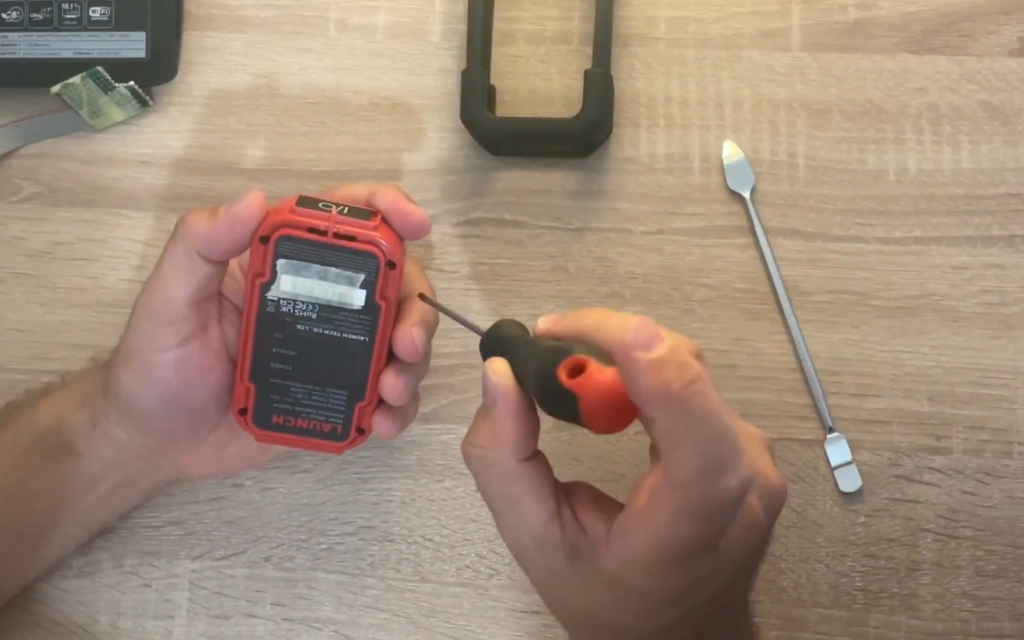
Opening the Housing
The DBScar 5 housing is plastic and held together with small clips. To open it, use a thin plastic prying tool or a phone-opening tool. Do not use a pointed screwdriver, as it can leave marks or break the plastic. If the adapter has a rubber protective cover, remove it first. Then locate the seams and clips along the middle of the housing and carefully insert the prying tool between the top and bottom parts. Work slowly around the housing until all clips release. Once open, you will see the PCB with the microcontroller and test points for programming.
Connecting to the Programmer
On the DBScar 5 PCB, there are connection points for ST-LINK V2 or J-Link programmers. These are usually labeled or presented as small round pads. Four key pins must be connected: GND, 3.3V, SWDIO, and SWCLK.
Connect the programmer wires pin-to-pin:
GND → GND
3.3V → 3.3V
SWDIO → SWDIO
SWCLK → SWCLK
If using a soldering iron, solder thin wires to these pads. If you don’t have one, small crocodile clips or pins can be used, but ensure a stable connection during flashing. Before connecting, double-check all wiring—incorrect connections can damage the microcontroller.
If using a soldering iron, solder thin wires to these pads. If you don’t have one, small crocodile clips or pins can be used, but ensure a stable connection during flashing. Before connecting, double-check all wiring—incorrect connections can damage the microcontroller.
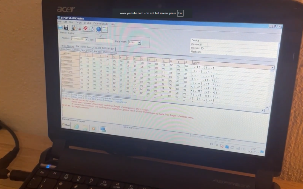
Flashing the Firmware
Once the adapter is connected to the programmer, plug the ST-LINK V2 into your computer’s USB port and launch STM32 ST-LINK Utility. The software should immediately recognize the microcontroller. In the application, select “Program” or “Load File” and choose the firmware file for DBScar 5 (ensure it is the correct file for this model, in .bin format). Click “Start” and wait for the process to complete. Do not disconnect the cables, move the wires, or turn off the computer. The flash usually takes less than a minute, and a success message will appear when finished.
Closing the Housing and Verification
Disconnect the programmer wires, clean any solder residue if used, and carefully place the PCB back into the housing. Close the housing so that all clips snap into place.
Now, insert the DBScar 5 into the vehicle’s OBD port and launch the X-Diag PRO application on your phone. Log in, enable Bluetooth, and connect the adapter. If a code is requested, it is usually 1234 or 0000. Once the adapter is recognized in the app, try running a diagnostic on a vehicle to ensure everything works correctly.
Troubleshooting
- If the programmer does not detect the microcontroller, check the connections and power supply.
- If flashing stops midway, try again from the beginning.
- If the adapter is unresponsive after flashing, the most common cause is incorrect firmware. Reflash with the correct file.
- If Bluetooth fails to connect, delete the old pairing in your phone settings and pair again.
Summary: The DBScar 5 is opened with a plastic prying tool, connected to ST-LINK V2 via the SWD interface, firmware is uploaded using STM32 ST-LINK Utility, and then the adapter is reassembled and used with X-Diag PRO.